Setup DFT Filter and
Optimizations Dialog
Functionalities:
- Design of lowpass, bandpass, highpass spatial filters
- 'Hand draw' filter function or generate with Butterworth
filter functions
- Transform filter functions
- Perform optimization for the "thinness ratio technique"
- Perform optimization for the "highpass filtering technique"
- Perform optimization for lens distortion correction
Basic usage:
- An Image Window must be opened in order to access the Setup DFT Filter
and Filter Optimizations
Dialog in the Tools menu.
- Set the spatial resolution of the image in the Calibration
tab, if w is intended to be used as
cycles/mm.
The spatial calibration is automatically filled from the image
metadata if available. If w
is used in pixels, this calibration value is indifferent.
- Press preview
 to see the effect of the filter. The default unity filter does
not alter the image, even though the image data is
forward and
reverse Fourier transformed.
to see the effect of the filter. The default unity filter does
not alter the image, even though the image data is
forward and
reverse Fourier transformed.
- Alter filter function. Either by double-clicking the trace
and adding points, or using the Generate tab.
- See detailed protocol here.
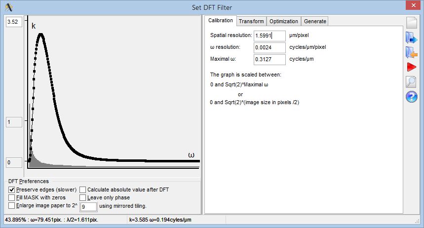
Dialog layout and Calibration tab:
Filter
function:
move points by mouse |
 |
| Scale graph by
dragging the '1' |
|
| Basic parameters of the
filter, see details
here |
|
| |
|
 |
|
|
|
|
|
Non-calibrated spatial frequency of pointer
position: |
|
|
|
-
% of Fourier domain
image in its diagonal (sqrt(2)*width/2)
-
w
in pixels
-
half wavelength (l/2)
corresponding to the w
|
- filter coefficient (k) and
w calibrated in
cycles/mm
|
|
|
|
|
|
 |
- reset to unity filter
- open filter (*.flt)
- save filter (*.flt) to load in
Multi-Dimensiona lOpen Dialog or in the
 2D DFT Filter
function 2D DFT Filter
function
- Process active image with the current filter
- Preview
- Online help on selected function
|
 |
|
'Calibrate' tab:
Set spatial resolution (x,y scaling) of the image
here. Alternatively the maximal or the per pixel
w can be given in
cycles/mm |
| |
|
|
| |
|
|
Transform tab:
- Scale function by the given factors
- Shift the function by the given offset
- Invert the function
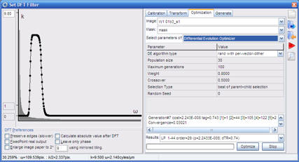
Optimization tab:
- Use Optimization tab to generate filter functions for the
optimized ratiometric spatial filtering, or thinness ratio
technique and highpass filtering technique
- The optimization works on an Image Window selected from the
Image Windows linked to the window active in the time of opening
the Set DFT filter dialog.
- The optimization requires the presence of an ROI on the
image
To perform optimization:
- Set target image
- Set mask image (which is a
binarized image where '1' is corresponding to the detail of
interest): Note: this is an optional parameter,
can be set by the "Use Mask" parameter of the selected function.
- Select 'Differential Evolution Optimizer' at the 'Select
parameters of' and set
parameters.
This controls the optimizer algorithm, and typically default
parameter are used.
- Select the function to be optimized ('Thinness
Ratio Filter Pair', 'High
Pass, Band Pass, Long Pass Filter' or 'Lens
Distortion Parameters') at the 'Select
parameters of' and set
parameters as described for each function (use the
 button to access help on function parametering).
- Press Optimize. Optimization may
take several minutes, while actual tested filter functions
briefly graphed in the dialog. Use ESC or the Stop button to abort it.
- When optimization is finished select the last two items in
the Results list and save filter
functions or note down parameters.
- See detailed protocol here.
Optimization of Lens distortion parameters:
- Select image to undistort as "Image" to align it to another image selected as "Mask"
(this is not a mask here). Typically "Image" and "Mask" show the same fluorescent structures, but recorded at different emission wavelengths. "Image" and "Mask" are eg. red and green channels, and the red is substantially distorted because of the chromatic/spherical aberration of the lens.
- Select at "type of correction" that which parameters are to be optimized and set the range of optimization below.
- Press Optimize. Optimization may
take several minutes. Use ESC or the Stop button to abort it.
- Copy optimized parameters from the Results list to
the Editing/Correct
Lens Distortion function.
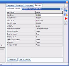
Generate tab:
The usage of these functions is identical to the ones with the
same names accessible from the Main menu/Filters.
To generate filters:
- Handle function parameters identically as for functions with
the same name using the
parameter bar of the
Main Window.
- Press the 'Generate' button to
update the filter function on the left according to the
parameters set in the Generate tab. The basic
parameters below the graph on the left side of the dialog will
be populated from the function parameters.
- Press 'Set as Default' in order to
reuse the parameters, when using the corresponding function from
the Main menu or adding to Pipeline.