An extensive set of tools supports accurate background
subtraction in single frame and time-lapse images, including
handling of non-uniform background in space and time, supporting
full automation, low light level imaging and removal of tiling
pattern.
The background of fluorescence image comprises of:
- Detector offset (this is a fixed value, but depends on the
settings of the CCD camera or PMT of the confocal microscope).
- Scattered light from the optics hitting the sensor
- Medium around the specimen and out of focus parts of the
specimen
- Background light in the room, computer displays
For low light level imaging: floating point arithmetic and
histogram interpolation ensures that no bit noise is introduced by
background subtraction, even if pixel intensities are in the single
digit range.
Example for non-uniform background:
 |
 |
|
|
| Non-uniform background because
of fluorescence of the medium |
Non-uniform
background removed by
high pass filtering |
|
|
To subtract background use the Filters/ Subtract
Background or the Background Subtraction,
Normalization, OD dialog. Many of the built in
pipelines provides one or more
pre-configured background subtraction steps.
Subtract
Background or the Background Subtraction,
Normalization, OD dialog. Many of the built in
pipelines provides one or more
pre-configured background subtraction steps.
The background level can be uniform in space, but scattered light
from the medium or from the specimen is typically inhomogeneous.
Handling non-uniform background in space:
- Record and subtract background image in the absence of the
specimen, and subtract Image or
Reference Image as background.
- Create a background image without recording a cell-free area
in multiwell plate or multi stage position recordings by
minimum or median projection.
- Use local background
subtraction techniques (see also
protocol).
The background is often non uniform in time, like fluorescence of
the medium can change during drug additions, or the background light
as people move in the room.
Handling non-uniform background in time:
- Use background subtraction as ROI average by frames
(if a larger ROI can be selected over the background)
- Use background subtraction as Percentile by frames
(this is the most convenient option as long as the
amount of details (bright pixels) compared to the background
does not change drastically during the experiment. E.g. if the
fluorescent signal vanishes during the experiment, use ROI
average by frames and not Percentile).
- The most advanced way of fully automatic background
subtraction is using the Mean of pixels below percentile
of max projection algorithm, that selects those areas
of the image as background that are the darkest for the entire
recording.
The Filters/Subtract
Background and the Background Subtraction,
Normalization, OD dialog also provides functionality for
temporal and spatial normalization, and for optical density
calculation in brightfield images.
Performing background subtraction
- Invoke the Subtract background dialog in the main
menu/Tools or in the toolbar:
 or
or

- Use the Filters/Subtract
Background which is identical in operation to the
Subtract background dialog.
- To use reference images, mark a single frame background
image as reference image by right-clicking the Image Window/Set
Reference Image/Background. Reference images are matched by
channel number. See or change channel numbers using the
Edit/Rename dialog. Optionally use the IO/Set
Reference Image and IO/Rename
functions.
- Alternatively, an arbitrary single image can be subtracted from image
sequences (if x and y dimensions match) using the Math/Image
Arithmetic Single Frame. For this function images does not
have to be linked.
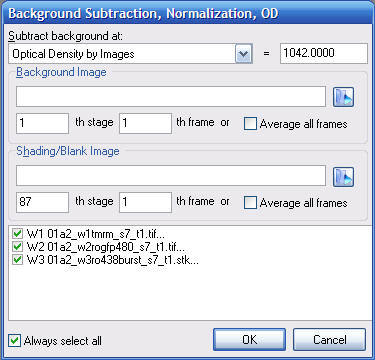
The Background Subtraction, Normalization, OD dialog
Methods of background subtraction, normalization or
optical density calculation
- Value: The entered value is subtracted from
each frame
- Image: Subtracts reference image. Matches
channels when using multichannel images including Metafluor *.inf data sets,
RGB images and multidimensional data sets. See also reference
images below.
- ROI average by frames: (set ROI number) The
ROI average (excluding masked areas) is calculated and
subtracted from each frame.
- ROI average by series: (set ROI
number) The ROI average (excluding masked areas) is calculated
for the complete time lapse and the same value is subtracted
from each frame.
- Percentile by frames: (in percents 0-100%)
The percentile of the image histogram is calculated and
subtracted from each frame. Typically use 5-10 percents. Don't
use this method if the fluorescent signal vanishes during the
experiment, and use the Mean of pixels below percentile
of max projection instead. Percentiles are calculated
with histogram interpolation therefore no bit noise is
introduced.
- Percentile by series: (in percents 0-100%)
The percentile of the histogram of the complete time lapse is
calculated and the same value is subtracted from each frame.
Typically use 5-10 percents.
- Percentile by frames ADAPTIVE: (in percents
0-100%) locally adaptive technique that tries to remove
calculated background, but keeps darker areas above zero by
decreasing locally subtracted background. Use high >90
percentile values for aggressive background removal. Don't use
this method if the fluorescent signal vanishes during the
experiment. Note: experimental algorithm, it didn't prove to be
useful.
- Percentile by series ADAPTIVE: (in percents
0-100%) locally adaptive technique that tries to remove
calculated background, but keeps darker areas above zero by
decreasing locally subtracted background. Use high >90
percentile values for aggressive background removal. Note:
experimental algorithm, it didn't prove to be useful.
- Normalization by Image: The Background
image (specified by its filename, stage and frame number) is
subtracted both from the current image, and from the
Shading/Blank image, then each frame of the current image
series is divided by the Shading/Blank image image. The
Background image should be recorded in the absence of
illumination (dark current) and the Shading/Blank image
is an evenly illuminated homogeneous field. If no Background
image is entered then the Value parameter of the dialog
is subtracted instead.
- Optical Density by Images: Similar to the
Normalization above, but the log((blank - background)/(current
image - background)) is calculated to reflect optical density
values in brightfield images. Use a dark current image
(illumination blocked) as Background image and and an
empty filed as Shading/Blank image.
- Normalization by ROI: normalizes to the
temporal changes of the mean of the selected ROI
- Refernece Image: Any open Image Window can
be set as reference image, by right-click (context menu) Set
as Reference Image/Background. Reference images are
not closed by Close All commands. The background subtraction
dialog will look for the first matching (in dimensions and in
channel number) reference image. The first frame of the
reference image is subtract from each frame of the selected
image. Use the Rename function to set the channel number if
required. Note: Create a background image without recording a cell-free area
in multiwell plate or multi stage position recordings by
minimum or median projection.
- Normalization by Reference Image: The
background reference image (see above Reference Image)
is subtracted both from the current image, and from the
Blank reference image (the reference image is not
modified), then each frame of the current image series is
divided by the Blank reference image. The
Background reference image should be recorded in the
absence of illumination (dark current) and the Blank
reference is an evenly illuminated image. If no Background
reference image is found then the Value parameter of
the dialog is subtracted.
- Optical Density by Reference Images:
Similar to the Normalization above, but the log((blank -
background)/(current image - background)) is calculated to
reflect optical density values in brightfield images. Use a dark
current image (illumination blocked) as Background
reference image and and an empty filed as Blank
reference image.
- Mean of pixels below percentile of max projection:
This is most advanced and robust approach, that is
applicable unsupervised. Working on a copy of the image
sequence, a binary mask is calculated from the maximum intensity
projection, according the the set percentile value. Then from
each frame the mean intensity corresponding to the pixels of
this mask is subtracted. Thus any moving objects will be
avoided, and only those pixels are used for background
subtraction that remained at background level for the entire
recording. This approach correctly calculates background when
fluorescence completely disappears during recording. Note: the
algorithm may be fouled by image registration algorithms only in
very noisy recordings. In this case use the "(dilated mask)"
version that avoids this.
- Median of pixels below percentile of max projection:
Similar to the above, but median is calculated.
- Mean of pixels below percentile of max projection
(dilated mask): Similar as above, but the mask is
dilated by 5 pixels, so it becomes insensitive to noise
smoothing caused by interpolation during image registration.
- Mean of pixels below percentile of max projection
(dilated mask): Similar as above, but the mask is
dilated by 5 pixels, so it becomes insensitive to noise
smoothing caused by interpolation during image registration.
Histogram and percentile calculation
Image Analyst MKII does not show histograms, but performs
calculation with histograms for scaling of Image Windows, background
subtraction and threshold calculation.
Set the histogram bins size (between 256 and 65536) in the
Preferences dialog Misc tab. Larger bin size results
slower scaling/updating of images but more accurate percentile
calculation. Given that the dynamic range of fluorescence microscopy
detectors is rarely above couple of thousand gray value units a bins
size of 4096 is more than enough.
To prevent introducing bit noise at low light level imaging, the
percentile calculation is interpolated between the bins of the
histogram. Therefore percentile values are always fractional, even
if an image contains only integer values. Because Image Analyst MKII
uses floating point pixel values, these fractional percentiles will
be correctly subtracted.
To enable/disable interpolation use the Preferences dialog
Misc tab.
Example for ROI and percentile background subtraction
Local background subtraction
Ways of eliminating non-uniform background:
- Subtraction of image background (see above)
- con: requires background image
- High pass filtering
- pro: fast and tunable, supports tiled imaging
- con: works well only if there is a lot of
background and there are no very bright spots on the
images
- Rolling ball style background subtraction by subtraction of median-filtered copy of the image
- pro: robust, more precise for intensity
measurements than the average-based rolling ball
background subtraction.
- con: slower than high pass filtering, but runs at a
reasonable speed on multi-core CPUs.
High pass filtering
Perform high pass filtering using built-in pipelines by
entering typical object size. High pass filtering is
independently applied to each frame and removes both spatial
and temporal inhomogeneities of the background. If the cuton
frequency is high, turn absolute value calculation on.
Additional percentile based background subtraction may be
needed for noisy images.
Tune a Filters/2D DFT Butterworth BP filter
using the Main menu/Tools/ Setup DFT Filter
and Filter Optimizations
dialog. See the
protocol for this.
Setup DFT Filter
and Filter Optimizations
dialog. See the
protocol for this.
Median Subtraction
Perform median background subtraction using built-in
pipeline. Median subtraction is independently applied to
each frame and removes both spatial and temporal
inhomogeneities of the background. This approach is more
precise for intensity measurements than the average-based
rolling ball background subtraction, that is more likely to
overestimate background and bias the intensity readout.
Removal of tiling pattern in background
Use image background subtraction:
- Record and subtract background image in the absence of the
specimen, and subtract Image or Reference Image
as background using the Filters/Subtract
Background and the
Background Subtraction,
Normalization, OD dialog.
- Create a background image without recording a cell-free area
in multiwell plate or multi stage position recordings by
minimum or median projection.
Use tiled high pass filtering, that independently filters
each frame of the tiled pattern. Note: this is efficient if
tiling is performed without overlaps :
Updated on 9/18/2015